Sometimes odd little things just crop up. I'm sure I knew about this before but it had slipped way below the radar. "Measure along an element" combined with Tab returns the length of a chain of elements. And into the bargain you get this quite impressive display of temporary dimensions. Not sure what I would do with it, but more data is better (apparently) so lap it up.

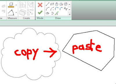
Then I read this post about copy-pasting revision cloud sketches into detail lines. SCRATCH PAD
I stumbled on this myself about a year ago, but haven't used it much. Just occasionally you want to cloud something that isn't actually a revision. Maybe it's a problem with the linked structural file, maybe it's just "we showed this feature two issues back but you seem to be ignoring it".
I was a bit surprised by the statement that you can use the cloud in a filled region. Doesn't work like that for me. You can paste the lines in alright, but all you get is the underlying polygon, no curvy segments.
But that led me to thinking, "what about a detail item". This was quite exciting, I thought I'd discovered a hidden gem. The curves came in perfectly and I even managed to get parametric scaling working.

Sadly though, despite the curves being fully intact in family editor, they don't transfer back to the project environment. It's just a rectangle.

Still, my mind was racing away by now. Isn't this really a lot like a line-based detail item ? So I quickly knocked one of those up and turned out to be surprisingly easy to get it working. Put this back into my rectangular rig and reloaded. It works, but something doesn't look right.

That's when I realised that the in the revision cloud segments, the meeting point between the two arcs doesn't lie on the straight line. No problem, this is also easy to set up.

Still, my little cloud was a bit too regular, so I threw in one of my false starts to mix it up a bit. Also set up a parameter for varying the proportions of the underlying rectangle.

All very good, and the journey was fun, but when I stopped to reflect, I decided that just drawing directly in the project with the line-based family was going to be the most effective strategy.
 But by now my mind was wandering all over the place. What about a two-pick family that defines a rectangle ? So I set up a rather elaborate rig with angles to define the proportions of said rectangle and tried locking lots of my little "2_arc_detail items" in place.

Of course that was asking a bit too much. Everything worked fine until I tried to change the angle, then it broke. Probably locking families to families I thought (by mistake) Easy to test, use the rig to drive a simple rectangular filled region.

That worked like a treat, so the principle is OK, but trying to lock 6 detail items each with 3 planes to be constrained was somewhat daunting. How many retries would I have the patience for? Wait a minute though. Locking a rectangle is easy enough and I already made a rectangular cloud. Just need to adapt that one.

This did the trick. Changed the rectangle family from 4 segments to six. Flexed it thoroughly. Nested into the diagonal-rectangle rig. Align and lock. And it works.

None of this is particularly earth-shattering, but it was an interesting exercise in squeezing unusual behaviours out of family editor. And along the way I came to realise what a neat idea the two-pick pair of unequal arcs was when someone on the original Revit team thought it up. If only we could recapture the freshness of those early insights. Wouldn't that be something ?
Oh yeah & I had fun with the snipping tool too.

Then I read this post about copy-pasting revision cloud sketches into detail lines. SCRATCH PAD
I stumbled on this myself about a year ago, but haven't used it much. Just occasionally you want to cloud something that isn't actually a revision. Maybe it's a problem with the linked structural file, maybe it's just "we showed this feature two issues back but you seem to be ignoring it".
I was a bit surprised by the statement that you can use the cloud in a filled region. Doesn't work like that for me. You can paste the lines in alright, but all you get is the underlying polygon, no curvy segments.

But that led me to thinking, "what about a detail item". This was quite exciting, I thought I'd discovered a hidden gem. The curves came in perfectly and I even managed to get parametric scaling working.

Sadly though, despite the curves being fully intact in family editor, they don't transfer back to the project environment. It's just a rectangle.

Still, my mind was racing away by now. Isn't this really a lot like a line-based detail item ? So I quickly knocked one of those up and turned out to be surprisingly easy to get it working. Put this back into my rectangular rig and reloaded. It works, but something doesn't look right.

That's when I realised that the in the revision cloud segments, the meeting point between the two arcs doesn't lie on the straight line. No problem, this is also easy to set up.

Still, my little cloud was a bit too regular, so I threw in one of my false starts to mix it up a bit. Also set up a parameter for varying the proportions of the underlying rectangle.

All very good, and the journey was fun, but when I stopped to reflect, I decided that just drawing directly in the project with the line-based family was going to be the most effective strategy.


Of course that was asking a bit too much. Everything worked fine until I tried to change the angle, then it broke. Probably locking families to families I thought (by mistake) Easy to test, use the rig to drive a simple rectangular filled region.

That worked like a treat, so the principle is OK, but trying to lock 6 detail items each with 3 planes to be constrained was somewhat daunting. How many retries would I have the patience for? Wait a minute though. Locking a rectangle is easy enough and I already made a rectangular cloud. Just need to adapt that one.
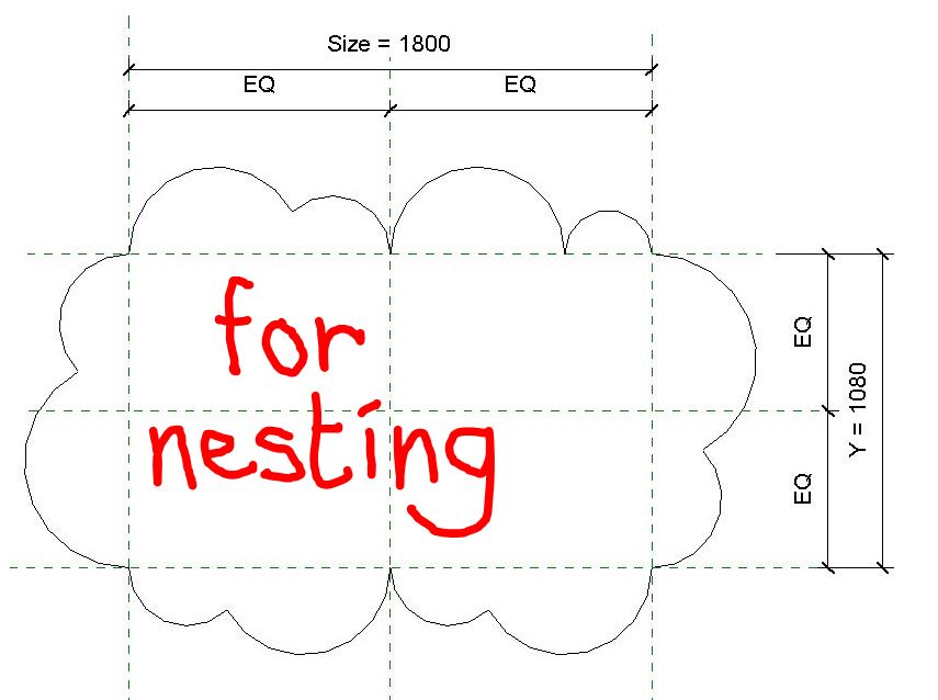
This did the trick. Changed the rectangle family from 4 segments to six. Flexed it thoroughly. Nested into the diagonal-rectangle rig. Align and lock. And it works.

None of this is particularly earth-shattering, but it was an interesting exercise in squeezing unusual behaviours out of family editor. And along the way I came to realise what a neat idea the two-pick pair of unequal arcs was when someone on the original Revit team thought it up. If only we could recapture the freshness of those early insights. Wouldn't that be something ?
Oh yeah & I had fun with the snipping tool too.


