Thursday, September 26, 2013

SAFETY IN GROUPS

Here's the scenario.  It's very common, and Revit doesn't have an ideal solution.  You are designing a hotel, or maybe an apartment block: any building with repetitive modular layouts, where each module contains 2 or more rooms subdivided by walls.  The construction technique is traditional wet trades, eg blockwork & plaster.


One solution is to use groups.  There are many disadvantages, especially when groups have to be maintained in several different buildings which are slightly different but share the same "typical units".  Another solution is to use links.  One of the downsides is that the walls will not join properly, you lose the self-healing property between walls in different files.  Ideally, Revit would give us the ability to enable self-healing of walls in links.  Perhaps this is a difficult coding problem.  Perhaps this type of construction is not commonly used in the US so it's not seen as an urgent issue.  I don't know, but I desperately need a solution.


In recent times, we have been maintaining two files.  The first file contains "Typical Layouts".  There may be 8 or 10 different types here.  Perhaps there are also 20 or 30 obsolete layouts, remnants of the design process.  It is a working area, but it is also the source of several sheets in our Concept Report.  Here we blow the rooms up to a larger scale and show more detail than in the General Arrangement plans taken from the project file.


The layouts themselves exist as groups.  Typically the surrounding walls are outside the group.  We don't want to duplicate walls as we copy the group around in the project.  So the project file consists of the outer shell of the building, plus the main dividing walls which separate the hotel rooms or apartments.


We used to place the modules as groups from day one, but now I prefer to delay that transition.  We place them as links, with the intention of binding them as groups later on when the cycles of design changes have run their course.  The downside is that we don't have clean joins in the GAs but we have learnt to live with that.

Last weekend I resolved to clarify my understanding of group insertion points and link origins in order to define a clear protocol for saving groups out multiple times as the designs develop, confident that the links would maintain their positions when reloaded into the project.  This is quite easy to do.  But along the way I had some interesting thoughts for "self-healing workarounds".


The first step was to disallow join, and pull the internal walls back to the core face of the surrounding wall, instead of jumping to the centre line.  This minimises the area of overlap.


My next idea was to somehow embed a detail patch in the group to clean up this junction further,  A detail item cannot belong to a model group, so I decided to embed the detail within a Generic Model.  The GM family contains only one model element, an "invisible centre pole".  You may be familiar with this device.  Because the cut-plane of the view intersects this invisible line, the detail item will become visible.


With a little tweaking, I soon had a family with parameters for wall thickness & plaster thickness, linking through from the GM to the detail item.  You can place it at wall junctions and lock it to the centre line of the partition wall.


One final trick is to join geometry inside the Typical Layout file.  Now you can have birds-eye cutaway views of the rooms with nice clean wall junctions.


The diagram below summarises the whole process.  I have yet to implement this in a live project, so there may well be problems that I have not foreseen, but I am optimistic that it will prove to be a useful technique.


I played with room separation lines & also a protocol for marking the origin point of the group.  Actually this all took place a few weeks ago and since then we've been implementing.  The idea of exporting from group to link repeatedly does not work well.  The buildings that the layouts are linked into treat the resulting links as totally new objects.  Any dimensions that reference them are lost.  So it's not a robust workflow.  In practice you need to make changes directly in the link files and load these back into the typical rooms file to make this update.


Rooms within the links cannot have unique numbers in the project.  This would also be a nice enhancement & I am guessing that it would be easier to code than the wall joining behaviour.  Make the rooms into separate groups, save as separate links.  Can be bound as groups at an early stage than walls etc.  Could be placed directly in project, but changes will be harder to manage.  Room numbers need not be added in the earlier stages.  Room group/link should also have an origin marker

To allow the rooms in the project to detect the walls of the links you need to select the link, go to type properties, check "room bounding".


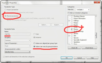
Normally the only parameter that can vary between groups is "room number".  One added bonus with 2014 is that we can now specify other parameters that vary between groups.  For example we could add a shared project parameter for rooms called "apt no"


Would be interested to hear how other people handle these scenarios.  These little workarounds are all very fine, but ultimately I am left feeling "there has to be a better way"

Thursday, September 19, 2013

INTERIOR AWARDS

GAJ Interior Design department won several awards this week confirming their position as leaders in the Middle East market.  In my experience it's much easier working with an in-house interiors team than external consultants.  We didn't have this capability 10 years ago when I first joined GAJ.  They started small and it's been a pleasure watching the department mature and grow.


You can read more about the awards event at the link below.


They have always been really strong at visualisation.  We have some first rate people working in Max who produce stunning renders, but until recently all the construction drawings were done using 2d Autocad.  I've been plugging away for some time at this and it's starting to pay off.  We have a couple of guys with Revit experience in the department and I'm running "evening classes" at present to extend this capability and form a really solid core group.  Has to be evenings, because we are just so busy.  

Keeps me out of mischief I guess :-)


Wednesday, September 11, 2013

POWER CONES - gherkin

This follows on from a previous post, where I used a Rectangular Rig to Graph a Function.  If you looked carefully you may have noticed how useless I am at formulas in Revit.  I mention this because you may find it encouraging.  If my work is the result of trial and error then maybe there is hope for you.  Something like that.

American History & Practical Maths

In my first attempts at a quadratic graph, I was too lazy to look up the symbol to use for "to the power of" and I just used Y1*Y1 for squared.  Later on I changed it to Y1^2 because I was getting embarassed about being so lame.  The good part of this was that it started me thinking about other powers and I realised that I could replace the 2 with a parameter.


Now you make one family and you can vary the curve increasing the "power of Y" or the "power of X" depending on which way up you make the graph.  Of course, if the power is 1 you will have a straight line (X=Y)  If it was less than one you would get a concave form.


Use this curve in a massing family (or Generic Model Adaptive) to create a revolve.  Looks like a coconut macaroon.


Now lay a whole bunch of them out and vary the parameters in a systematic manner.  I've taken care to organise the parameters so just 3 of them display to the end user.  Here we are keeping the base width constant and varying the other 2:  power & height.


Of course you can generate much more variety by manipulating all three and taking them to extremes.


Here's a view that shows what we are doing more clearly.  I was quite excited by this, but if you look closely the curves are not quite smooth.  There is a certain amount of "necking" taking place at extreme values.  Unwanted bulges.


Seemed to me this was a result of not having enough points to hold the curve steady.  So I set about making a more finely divided rig, which gives me a chance to talk you through the process.

Two points created in an elevation view.  Labelled dimension gives me a height parameter.  Spline thru points joins them with a ref line.  Set the work plane to the vertical plane of each point in turn.  Place points on points, give them offset values.  Label these with a width parameter.  Complete the rectangle.  This is a classic rectangular rig.  See also the video on my Vasari Talk session.


I'm creating vertical rungs using Normalised Curve Parameter positions  that are assigned parameters (x1, x2, x3 etc)  Initially these create 10 equal divisions (0.1, 0.2, 0.3 etc)


Then I string a spline across these rungs.  These points get parameters too (y1, y2, y3 etc)  Now you can linke X & Y with a simple formula to generate a regular curve.  That's what I did before with 5 divisions.  Now I have a finer degree of control.


Power of 2 gives us a nice smooth parabola.


Power of 6 concentrates most of the curve in the "middle".  You get a relatively straight section, then a sharp bend, then an almost flat top.  This is where the anomalies start to show up.  At power of 9 the curve starts to reverse because there aren't enough points to hold its line. (see how it flares out slightly at the base)


I dealt with this by making the points closer together near the ends.  It's kind of like using a logarithmic scale on your graph.


All good, but what if I want the curve to go beyond the vertical.  This is what I did previously with the Gherkin  (see the link at the beginning of this post)  It's a bit of a hack, but it works.


So I set this up and created a much bigger array.


The results are quite interesting:


a wide range of forms ranging from Gherkin-like shapes to onion domes,


all from the same family and just by adding a 4th parameter called "Waist Height"


Want to take a look ?  Click on the link


Tuesday, September 3, 2013

THE WAY WE BUILD : RONCHAMP

40 years ago I turned my back on the middle class safety of a professional career.  Like many teenagers of the 1960s I believed in the power of youth to build a new kind of society.  I spent most of the next decade laying bricks, playing guitar and drawing cartoons for mildly subversive publications.  Along the way I became fascinated by building trade processes and fell in love with the victorian terraces of the industrial north that I was renovating and extending.to earn my keep. I was intrigued by the variations in materials & technology as you moved from town to town,  In south yorkshire, wooden gutters and welsh slate roofs were the norm.  Further east in Lincolshire, cast iron gutters & clay pantiles took over.  It was also clear that modernity was sweeping away these subtle expressions of local character.  Plastic gutters and interlocking concrete tiles ruled the day.


30 years ago I changed course again, volunteering to teach at an experimental school in newly independent Zimbabwe.  I was teaching building, theory and practice, an exciting and challenging experience that swept me through my thirty somethings.  I wrote & illustrated text books, set exam papers, trained teachers, still laying bricks and absorbing a very different social world and different methods of building.


20 years ago I came full circle, finally registering as an architect.  But it was more of a spiral than a circle.  1990s Africa was a very different context to be an architect in than 1970s Britain.  I felt that I was making an important contribution to an emerging society, still full of optimism for the Zimbabwe project.  And at the back of my mind, a grand project was emerging.  To combine my experiences as builder, teacher and architect under the title "The Way We Build"

You can interpret this phrase in at least two different ways:

 BUILDING AS A PROCESS.  A sequence of activities.  Focus on how things are assembled, how tradesmen work.  Too many text books just show finished details with hardly a hint as to the how and the why.


WE ARE WHAT WE BUILD.  Architecture reflects the values of the society that originates it.  It is a mirror into the sould of human history.  Walk through any historic city or town: London, Amsterdam, Cape Town, Katmandu, and glimpse a whole series of transitions and power struggles that helped to lead us to where we are today.


10 Years ago Zimbabwe was imploding.  If you believe the recently announced election results, people have forgotten the devastating hyperinflation that dominated our daily lives.  Those with access to forex were building mansions thanks to multiple exchange rates.  I was struggling to maintain my lifestyle in my ageing post-war bungalow.  In the next street, a couple were living in a black plastic "tent" and selling tomatoes and cigarettes by the road-side.  Within a year I had escaped to Dubai and the chance to earn money for my children's university fees.  The culture shock was extreme.  From first gear to overdrive in the blink of an eye: a different climate, a different culture, different design imperatives.  flat roofs, wooden gargoyles, wind towers, glass skyscrapers rising from desert sands.


For most of the past decade I have been using Revit on a daily basis, teaching others, driving forward the BIM initiative.  Very soon I realised that this is also the ideal tool for my spare time research project.  Spare time is not the most abundant commodity in Dubai, but I have made some progress.

Almost 2 years ago I set about modelling Corb's famous chapel at Ronchamp, a building that is almost exactly the same age as me.    our-lady-up-hill

Recently I have has requests from architecture students to share that model, so I quickly posted a DWF and then set about cleaning up the Revit model.


I quickly realised that it would be better to start again.  The whole thing was oversized by about 10%  I don't have authoritative dimensional information, but based on a site plan with a scale bar and google earth imagery I was able to make a reasonable guess.  Several sources agree that Corb used a regular grid.  I have estimated this to be based on a 4.7m square.  It's probably wrong, but hopefully not by too much.  It's an regular grid. 6 bays by 8, but displaced half a bay.  It's usually better to have a bay in the middle of your building, not a grid line.  You'd rather put a door at the centre of your elevation than a column.  Corb often used this trick of putting half bays at the edge.


Having established a grid he usually proceeds to dance around it.  Grids should liberate, not constrain.  Free plan, free facade.  This is the kind of positivist philosophy that informed my youth.  Small wonder that I left university believing that we could change the world with free love and brown rice.


Holding hands as they dance around the back are a mother and her 2 children. AKA the 2 towers, periscoping light down onto 3 plain altars.  The North & West facades (which are anchored by these towers) are the solid elements in the design, blank & convex.  The South & East are lightweight, concave, welcoming.  I'll return to this, but first a diversion,


Some would have you believe that the word "Model" has killed more fluffy chickens than the dreaded "ATM Machine"  Actually it's a word with ancient roots, and of the 3 ancestors of the acronym BIM it is the only one with 2 dimensional origins.  Information is about giving shape and goes right back to the Latin, Build has old german roots, referring to a house or dwelling.  Model comes from Old French for a set of plans and goes back to the Latin Modulus.  So Model & Module are closely related.  None of this matters much though because words cannot sit still and what counts is the space where they are currently fidgeting around.

In curent usage a model is an abstraction, usually active as in a financial model or mathematical model.  You want to understand something complex and messy in the real world so you substitute something much simpler that you can poke with your fingers in the hope that it will capture some essential behaviours from the real world.  Imagine that this salt pot is the sun, this pea is the earth, this grain of rice is the moon, now a lunar eclipse ...  You don't care that the salt pot is not round & covered in flickering flames.  You are making bold leaps of faith in search of deeper insights.


So I am making an abstraction, a diagram that can help us to better understand what Corb was doing with this design.  I have to make judgement calls about when & where to simplify.  One of these concerns the 3 towers.


I need them to be symmetrical about a central axis.  That's not how they really are but it's a relatively minor adjustment that will make modelling 10 times easier and allow me to focus my efforts on the design rather than trivial technicalities.

Symmetry about an axis allows me to model the domed top as a revolve.


The profile is sketched by picking edges of the walls below.  These walls are composed of a series of short arches, making good use of the much neglected "Tangent End Arc" tool.


Revit contains a wonderful box of pencils.  They pop up whenever we enter sketch mode & also when building walls.  One of these pencils is often overlooked.  For several years I hardly ever used it.  If it were a real pencil it would still be full length while the "3 point arc" had been worn to a stub.  But more recently, "Tangent End Arc" has become my best friend.  For Ronchamp it has been indispensable.


From there I cracked on fairly quickly, copy-pasting some elements from the previous model and scaling them down slightly where necessary.


Now comes the roof.  A serious rebuild is called for.  Previously I only modelled the lower surface.  In fact I had originally assumed that this was all there was.  Towards the end of my first attempt I realised that the roof is a double skin with internal ribs.  Since then this has been confirmed by a number of references that I have stumbled upon.  Corb himself compared it to aircraft wing construction.


I thought I might start with these ribs this time and chose to make them as walls shaped with the Edit Profile feature.

You can see that the South Wall also has a skeletal structure and I have reason to believe that what we see from the outside is also a thin skin, basically ferro-cement, a sand-cement mixture thrown onto wire mesh.  Years ago I had a friend who made magnificent garden sculptures of giant birds using this method.


So I brought in the lower surface from my previous model.  It's an in-place mass, lofted from a series of splines.  I used the old fashioned kind of spline, not the new, point based kind that only exists in conceptual massing.  The surface is in 2 pieces and they share one spline which runs along the mitre where they join.  That's the only way I could get it to turn the corner with a sharp point at the south-east corner.  Corb compares this to the point of a 3-cornered hat.  (Liberty, Equality,Fraternity)


There must be some cross ribs to support the cantiliver over the open air altar facing east, but I don't know how many.  The only sketches I have ever seen of this ribbed arrangement are extremely vague and ambiguous.  At the moment I just have 2 and I have placed them directly over columns for which there is clear evidence.


For structural reasons I have tied them back to the second major rib.  That's the only way to make a cantilever work.  Like the jib of a crane, you need some weight on the back end as a counterbalance.


Perhaps these secondary ribs travel the whole length of the building, dividing the whole roof into a series of rectangular cells.  That would make a lot of sense, but I haven't implemented it yet.  Would be nice to have some evidence.

Turning to the South Wall.  I have a column family that I made last time.  The height can be varied, and the base width, but the top remains the same size, and centred on the axis.  In other words I have separate parameters for front & back base offsets.


The wall itself will be an in-place mass and will follow the shape of the columns fairly closely.  I have a much better understanding of how to loft with profiles now than I did 2 years ago, so I started again.  I made a mass family that just contains point-based model lines.  The arrangement of parameters is basically the same as the column family.


I place one of these profiles on each grid and adjust the parameters so that the wall is a bit wider than the column.  Select the first 2 and "create form".  Select this form and the next profile.  Create Form again.  Keep going and adjust them one by one until you have a smooth form covering all the columns.


At this point I realised that the top of the wall had to slope.  It was OK for the top of the columns to be flat, but there is a small gap between the wall and the roof, a slit where the light comes in.  The top of the wall has to slope like the surface of the roof above.  I added a "Top Slope Offset" parameter to my mass profile family.


There followed a process of adjusting multiple elements (columns, beams, mass wall) until they all match up.  This would be repeated again later when I realised that the roof wasn't right.  It all takes time but along the way you find you are understanding the building at a much deeper level.


Back to the roof now.  The surface has to be cut by a void extrusion alonng the North & West sides.  Cut by the embrace to the mother and her 2 daughters.


To give the lower surface thickness use roof by face ... sadly it doesn't work.  It's quite well known that wall by face is more stable than roof by face, I'm not sure why.  Perhaps it has something to do with the fact that roofs have to accept wall attachments.  Anyway, wall by face is what I used.

Then I decided to do a bit of a render, combine it with a realistic view, and play around with some image processing.


The North Wall was coming along quite nicely, but I'm failing to reconcile the structure with the window & door openings.  Surely the major beams need supporting columns.  These are probably cast between the stonework as it is built (as opposed to building the columns first and infilling with masonry later)  I have some photographic evidence for this.  But there are doors and windows where the columns should be.  Maybe the columns are shifted off grid and there is a tie beam across the top of the wall that carries the ends of the major ribs.  Just speculating.


I took a break and brought in the topo from the previous model.  Time for a little reflection.  The building is closed in on 2 sides by solid masonry, actually the stone blocks from a ruined chapel that stood here before.  These blank faces are also where the cellular spaces are clustered: the smal chapels, confession booths, 3 rectangular rooms stacked one above the other.

Two sides stand for enclosure, mass.  They belong th the earth, the flat plane below, solid and supporting, opaque.  3 sides of the box are closed.  The other 3 sides partake of the sky, light and floating, welcoming, concave, pointed, hollow.


Top surface of the roof now.  I experimented a bit with point based splines this time.  Seemed like a good idea, but ultimately I decided that traditional splines are better for this particular situation.  For one thing they are planar, which is what I want, except for the one curved edge at the extreme eastern edge.  That has to be spline by points.


So I got the top surface in and adjusted the profiles of the rib walls.  There goes another hour from my life.  Lots of playing with sections and section boxes to try to get the alignments as close as possible.  Using the Tangent-End-Arc tool again to create smooth curves.  Maybe I should have tried splines.  It's a real shame that Roof by Face didn't work.  I could have just attached the walls top and bottom.  Thinking about it though, that wouldn't fly.  The lower surface goes vertical and beyond over the south wall.  That's probably why Roof by Face didn't work in the first place.  Doesn't make sense to attach the bottom of the wall to a vertical surface, never mind an overhanging cliff face.


I was feeling very proud of myself.  Lots of hard work but I have this nice ribbed double-skin roof to show for it.  Sadly it wasn't quite right.  Set up a view and check it against a photograph.  Needs to be more triangular (from this viewpoint).


So enter another round of adjusting roof surfaces and editing the profiles of rib-walls.  The curves of the bottom surface are much more extreme that you might think.


I needed a break, so back to the towers.  Originally I had made the front faces as walls, and attached them to the revolves at the top which are in the Roof category,  Getting into more detail, it turns out that the walls have splayed reveals, just at the top.


Tried a couple of ways to do this, but it got messy; so I decided to model the whole of the top portion in place.  Mostly extrusions, some horizontal, some vertical, including the windows with the rows of tall thin panes.


So let's tackle the splayed windows in the south wall.  Splays within splays.  That's tricky.  First of all I set up 2 working plans which approximate the inside and outside surfaces of the wall (which are not planar, but twisting curves.


Next is a rectangular profile (mass category)  X & Y dimensions are instance parameters.  Place one on each plane, a small one & a big one.  Select them and create void form.  Rinse & repeat.  To help with this I set up a sheet.  Three of the best reference images I have plus a live view to work in.


The openings are not perfectly rectangular, because the working planes don't quite match the surfaces of the walls.  But they are pretty good, and by doing this exercise in 3 dimensions you come to appreciate the complex interplay between these splayed windows and the horizontal beams that run between the columns.


So let's go back to the paired images.  These look much better now.  Not perfect, but much better, and I've learnt a lot on the way.


What about the interiors ?  I had to do a similar exercise with them.  One again not perfect, but quite revealing.


I need to put a gentle slope on the floor, and some model lines to represent the joints in the floor.


At this point it was a welcome relief to do some straightforward modelling.  A couple of fonts, the external pulpit, main entrance door, north entrance door,  All these are quite interesting as architectural accessories.  So many little details in this project, you have to admire Le Corbusier's vision and commitment.  This is not a big money commission.  Everything is kept very basic.  This is a pilgrimage church belonging to a monastic order that doesn't have a lot of money.


I love the way that he handles off-shutter concrete and roughcast rendering to give this chapel a simple majesty.  As far as I know he was a lifelong atheist with left-wing sympathies.  It's interesting that it should take a guy like that to express the humility & grandeur of the christian cause in a modern idiom.  I am not religious myself, but I am interested to understand the grip that religions have had on human society over the ages.  Perhaps that's how Corb felt.  Perhaps he enjoyed the human dimension.  Perhaps he was also drawn to the communal values of monastic orders (think La Tourette)


So I have reached a point where I am ready to share my work.  I thought of limiting access, perhaps forcing people to register to my blog before they could download.  In the end though, once it's out there people can pass it around.  And I only want people to register if they feel like it.  Corb gave us (the whole world) a fascinating building.  I have used BIM software as a research tool.  I think more people should be doing this.  Architectural departments around the world should be doing this.  I would like them to do it openly.  We would all benefit.  In that spirit, I am making my work freely available.


I finish with a sectionalised axo that offers an unusual viewpoint.  You can see things you might not have noticed before.  The extreme curves of the double shell roof perhaps.  The doubled-up doors between the daughter towers to the north ... why is that ?  acoustic privacy ? not really because the baffles above are not glazed.  They allow air to circulate, while keeping out the worst of the rain and creating an effect of indirect, filtered light.

Lots of questions remain.  I hope people will contribute to discussing these.  Perhaps you have answers.  Perhaps you have interesting speculations.  Perhaps you want to model aspects that I have not yet tackled.  There are further comments and questions marked up on the sheets within the Revit file.  This is 2014 format.  Sorry for those who don't have, but that's what I use now.

get the download       REVIT FILE HERE

there is also an updated DWF version    HERE