It began as one of those little jobs for a friend of a friend. Enhance a small studio apartment with a deck over the kitchen accessed via a spiral stair, working from a couple of photos and a thumbnail sketch. An ideal chance to try out my adaptive family thought I.

The basic situation is as shown above, which I knocked up quickly enough. The apartment is quite interesting in that it has a vaulted ceiling. For this exercise it was simplest to make this as a solid block cut through in 2 directions. In practice this was modelled in-place as an extrusion cut by a void at right angles. You can copy-paste the shape of the arch from the extrusion sketch to the void sketch so they match.

Once I remembered how it worked, my adaptive family proved very useful. The ease with which you can vary the height, radius, angle of revolution, no of risers etc is ideal for exploring design options on the fly. Here you can see a comparison between 12 & 13 risers to reach a deck set at 2400. (the last riser is the deck itself)

It took me a while though to recall what I had done. The tread assembly is a generic model embedded in a curtain panel. The curtain panels themselves are loaded into a helical divided surface. You have parameters to control the number of divisions and the angle of turn. One edge of each panel is always vertical. This represents the central pole of the staircase. So the trick is to lock the embedded tread to this vertical side so that it will always remain true while the other relationships are varied.

Within the tread component, the vertical baluster with its nut at the end is again a nested component. The height is controlled by a linked parameter. There is also a spacer, between the treads, basically a tube slotted over the baluster. Perhaps I should have made this inside the baluster component, but that would have meant at least 2 more linked parameters, and I was too impatient, so I modelled it directly in the tread family. As a result it tends to drift off centre.

How do you lock a circular extrusion to a nested family ? This seemed like an interesting challenge, so first I created reference plains controlled by a "baluster offset" parameter and locked the baluster to these. Easy. Then I found that if you create a circle from two semicircles, you can also lock these in place. Have you noticed that Revit often makes circles in two pieces ? Perhaps this is why.

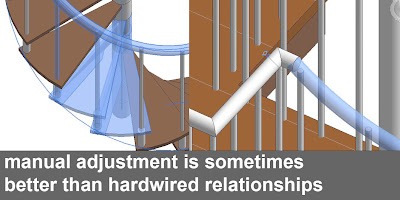
I had also forgotten that there are separate controls for the handrail radius and the tread angle which you have to fine tune once you have set up your basic configuration. I could have hardwired these relationships into the family, but I opted for manual control which means you can tweak things visually to line them up. One of the frustrations of Revit's system tools for stairs and railings is the way that relationships are automatically calculated. It's great when it works, but sometimes it would be nice to select an individual baluster and nudge it to the left a bit.
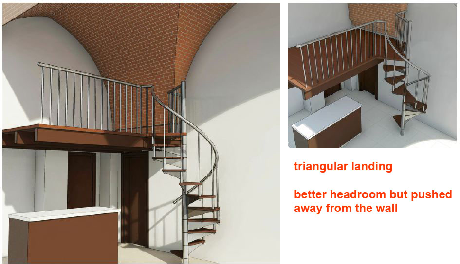
Getting back to the design problem itself, I learnt some interesting stuff about spiral stairs. The solution I inherited had a square landing, which has certain advantages, but makes for tight headroom. A bit of web research revealed that many of the spiral stair kits use triangular landings. Again my adaptive family proved very useful for quickly comparing these 2 solutions. You get better headroom, but the stair is pushed further into the room.

To understand this better I took a break from 3D and produced some simple diagrams in a drafting view.

BIM is great, but we shouldn't forget that orthographic projection is also a very powerful tool, and sometimes a simpe abstract diagram is more effective than dozens of photorealistic images.

So a weekend's work produced two solutions to the problem, all nicely presented in both orthographic and glorious 3D.

The relative merits of triangle and square were clearly illustrated.

Personally I was leaning towards the triangle.

Turns out I had misunderstood the intention completely. The stair was supposed to go on the other side. But that was OK. Took me about an hour to make the change, including some rendering. and the inevitable adjustments to annotations when you reverse a section.

Incidentally, there's an image in there that I'm quite proud of. It involved blending three jpegs ( 2 renders and one shaded) The timber deck is switch off for one of the renders, and set to ghosted in the shaded view. All 3 views contribute to achieving the right balance of transparency in the final image.

So apologies for the break in transmission. I went on leave and have been swamped since I got back. Hopefully I can resume regular posting now. By way of compensation here is a link to my adaptive spiral stair.
adaptive spiral stair.rvt
Have fun breaking it & let me know how you get on.

The basic situation is as shown above, which I knocked up quickly enough. The apartment is quite interesting in that it has a vaulted ceiling. For this exercise it was simplest to make this as a solid block cut through in 2 directions. In practice this was modelled in-place as an extrusion cut by a void at right angles. You can copy-paste the shape of the arch from the extrusion sketch to the void sketch so they match.

Once I remembered how it worked, my adaptive family proved very useful. The ease with which you can vary the height, radius, angle of revolution, no of risers etc is ideal for exploring design options on the fly. Here you can see a comparison between 12 & 13 risers to reach a deck set at 2400. (the last riser is the deck itself)

It took me a while though to recall what I had done. The tread assembly is a generic model embedded in a curtain panel. The curtain panels themselves are loaded into a helical divided surface. You have parameters to control the number of divisions and the angle of turn. One edge of each panel is always vertical. This represents the central pole of the staircase. So the trick is to lock the embedded tread to this vertical side so that it will always remain true while the other relationships are varied.

Within the tread component, the vertical baluster with its nut at the end is again a nested component. The height is controlled by a linked parameter. There is also a spacer, between the treads, basically a tube slotted over the baluster. Perhaps I should have made this inside the baluster component, but that would have meant at least 2 more linked parameters, and I was too impatient, so I modelled it directly in the tread family. As a result it tends to drift off centre.
How do you lock a circular extrusion to a nested family ? This seemed like an interesting challenge, so first I created reference plains controlled by a "baluster offset" parameter and locked the baluster to these. Easy. Then I found that if you create a circle from two semicircles, you can also lock these in place. Have you noticed that Revit often makes circles in two pieces ? Perhaps this is why.

I had also forgotten that there are separate controls for the handrail radius and the tread angle which you have to fine tune once you have set up your basic configuration. I could have hardwired these relationships into the family, but I opted for manual control which means you can tweak things visually to line them up. One of the frustrations of Revit's system tools for stairs and railings is the way that relationships are automatically calculated. It's great when it works, but sometimes it would be nice to select an individual baluster and nudge it to the left a bit.

Getting back to the design problem itself, I learnt some interesting stuff about spiral stairs. The solution I inherited had a square landing, which has certain advantages, but makes for tight headroom. A bit of web research revealed that many of the spiral stair kits use triangular landings. Again my adaptive family proved very useful for quickly comparing these 2 solutions. You get better headroom, but the stair is pushed further into the room.

To understand this better I took a break from 3D and produced some simple diagrams in a drafting view.

BIM is great, but we shouldn't forget that orthographic projection is also a very powerful tool, and sometimes a simpe abstract diagram is more effective than dozens of photorealistic images.

So a weekend's work produced two solutions to the problem, all nicely presented in both orthographic and glorious 3D.

The relative merits of triangle and square were clearly illustrated.
Personally I was leaning towards the triangle.


Incidentally, there's an image in there that I'm quite proud of. It involved blending three jpegs ( 2 renders and one shaded) The timber deck is switch off for one of the renders, and set to ghosted in the shaded view. All 3 views contribute to achieving the right balance of transparency in the final image.

So apologies for the break in transmission. I went on leave and have been swamped since I got back. Hopefully I can resume regular posting now. By way of compensation here is a link to my adaptive spiral stair.
adaptive spiral stair.rvt
Have fun breaking it & let me know how you get on.
No comments:
Post a Comment
I've been getting a lot of spam so had to tighten up comments permissions. Sorry for any inconvenience. I do like to hear from real people